Jack Heavy Duty Table Assembly
Introduction
Assembly Instructions
Required Tools

To assemble your table you will need the following tools:
- Screwdriver (Normal Length)
- 8mm Wrench
- 10mm Wrench
- 14mm Wrench
- 7/64 inch Drill Bit
- Electric Drill/Screwdriver
- Ruler
- Pen/Pencil
Box Contents
Your table will ship in a separate box from your machine head and come packaged with the following:
- Heavy Duty Table
- Stand Legs x2
- Stand Legs Brace (w/ "Jack" logo)
- Foot Pedal
- Foot Pedal Brace
- Storage Tray
- Package of Nuts, Bolts and Screws
Your machine box will include:
- Machine Control Module
- Adjustable Rod for Control Box to Foot Pedal
- Thread Stand
- Knee Lifter Pad (Non-Automatic Units)
- Knee Lifter Umbrella (Non-Automatic Units)
- Oil Pan (If Not a Sealed System)
- Oil Pan Magnet
- Oil
Stand Assembly


Take x6 of the bolt washer combos and x2 of the stand clamps to assemble the stands legs. You will use x3 of the bolts and one stand clamp per stand leg.

The stand clamp must be placed inside the legs channel and aligned with the bolt holes on the opposite side. Depending on the height you want the table to sit you have two seperate set of bolt holes to choose from (we suggest using the upper two). Screw in the two bolts hand tight. Screw in the last bolt on the side of the stand leg. Do this for both legs.


Adjust the desired height of the legs with the hash marks located on the outside of each leg and align them to your desired height. Once you are satisfied with the selected height; fully tighten the bolts using a 14mm wrench. Tighten the two outside bolts first then the single bolt.

Orient the table to match the picture below. This step is important since we will be measuring guide lines based off the orientation of the table to align the stand legs. The intersecting points of the lines will be guides of where to place the stands legs. We will reference RIGHT and LEFT as we stare at the table in this orientation.

From the very left edge of the table measure and square up and down 5 inches. From the back of the table measure 2 inches and square across.

From the right side of the table measure in 10 inches and square up and down.

From the front of the table measure 4 3/4 inches and square across.

Once the guidelines have been created align the stands legs so that they sit on the inside of the guidelines. With a pen or marker, mark the center of the mounting holes. Do this for each leg.

Once the mounting hole marks have been created we will use them as a reference of where to drill small holes for the stands mount screws. Take your 7/64 drill bit and using the center of the reference marks, drill a small hole 1 inch deep.

Align the LEFT stands leg on the inside of the guideline and make sure your drilled holes are about center of the mounting screw holes. Take your mounting screws and slowly screw them in place using a 8mm wrench. These screws are not designed to handle high torque forces and MUST be done by hand. Screw the LEFT leg until there is no side to side movement.

Before mounting the RIGHT leg we must prepare the leg cross brace.
Take x4 of the bolt washer combos and the cross brace. Place the cross brace with the "JACK" logo upside down (once the table is flipped right side up, the logo will be oriented correctly) on the back of the stands legs and tighten so there is a bit of free movement. We will not be tightening these bolts until after tightening the RIGHT leg.

Now it's time to alight the RIGHT leg to the inside of the guidelines and tighten them using x2 mounting screws and the 8mm wrench. Again, tighten until there is no side to side movement of the leg.
Once both legs mounting screws have been tightened its time to tighten the cross brace. Take your 14mm wrench and tighten all 4 bolts until there is no free movement of the brace on the stand. Tighten an additional 1/2 turn to torque the cross brace securely.
With the stands legs now securely in place we can assemble the foot pedal.
Take the long slotted cross brace (this is what the pedal will mount to) and place it toward the front of the stands legs. A good reference point is to place it so it almost touches the legs blue protectors. This brace can be moved forward and backward to adjust how far inward the foot pedal sits.

Be sure to orient the cross brace hardware as seen in the image below. The silver clamp must have the protrusion to the outside or the clamp will not fully grab and secure the cross brace. Once you are happy with the position of the brace secure the bolt using a 14mm wrench until the brace is secure in position. Do this for both sides.

To assemble the pedal you need x2 of the 10mm bolt washer combo, the pedal lever mount and the pedal.

We find it best to place the pedal lever mount on the right edge of the pedal. Take your 10mm bolt combo and orient them so that the nut is on the outside of the lever and the screw is on the inside. With a screwdriver secure the bolt and with a 10mm wrench fasten the nut. This should be done for both slots of the foot pedal lever mount.

To mount the foot pedal to the slotted cross brace you will need x2 of the foot pedal pivot mounts and a nut and bolt set. We find that for majority of our customers prefer to mount the foot pedal in the center of the cross brace.

Place the foot pedal pivot on the cross brace so the tab sits inside the slots of the cross brace; the cylindrical pivot piece should be oriented so that they are both facing each other. Hand tighten the pivot so that they move freely and slide the foot pedal into each pivot. Finalize your desired foot pedal placement and tighten the pivots in place. In the image below the table was turned right side up to show orientation of the pivot and pedal. Be sure once pivots are secured that the foot pedal moves freely.

Inside the machine box you will find the control module with mounting screws. The control module in the image below is for a Jack A4. Mounting procedure is the same for all control modules.

Take your control module and attempt to align both the control module lever and the foot lever. They do not need to be exact as the rod that connects both levers together has ball joints that can accommodate some movement.

Align the edge of the control module mount to the 2 inch guideline we made previously made. Using the 3 included screws, mount the control module to the table.


Inside the machine box is a adjustable rod with ball joints on both ends, this will be used to attach both the control module and the foot pedal together. Loosen the middle adjustment screw so you can freely adjust the length of the rod while you secure the ball joint rod ends.


Secure the ball joint ends to each lever as shown in the image below. The orientation does not need to be exact, but try to maintain alignment with the control module lever and the foot pedal lever.


To adjust your foot pedal to desired angle for sewing: loosen the middle adjustment screw and set the angle of the foot pedal to the desired start point. Check that the foot pedal is able to actuate the control modules lever full range of motion before tightening. Once satisfied with desired pedal angle, fully tighten adjustment screw.
Optional Step (Machines with Birds Nest Prevention)
If your machine comes equipped with a Birds Nest Prevention System this is a required step for set up.
Find the smaller control module for the electric suction device.

Find the small magnetic adapter and slide it on the adjustable rod, keeping it a few inches away from the control module. Tighten the two allen screws to secure it in place.

Take the suction control module and align it next to the machine control module so that the blue piece is only a few millimeters away from the magnetic adapter.

Optional Step (Machines with Sealed Oil System)
Take the plastic protective housing found inside the machine box and mount it to the underside of the table using x4 of provided screws.
Stand Assembly Continued
Flip the stand right side up.
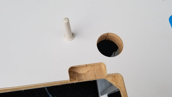
Find the cylindrical cone shaped peg inside the machine box. This is the peg that the machine rests on when it is tilted on its side. Place the peg inside its hole.

Sealed Oil System
Find x4 rubber machine pads and x2 rubber pivot pads, there will be two of each shape.
If you have a sealed oil system on your machine head like on the Jack A4S or the Jack A5 units the rubber machine pads will be solid. Simply place the pads in their respective areas and secure them in place with the provided nails.


Unsealed Oil System
If you have an unsealed oil system the x4 pads that sit on each corner will have slots on the sides of them. Take the oil pan and slide the rubber machine pads into place before mounting the oil pan with pads to the table. Once mounted secure the pads in place with the provided nails.


